PHOTOVOLTAIC CHECK-UP
![]()

PV MODULE PERFORMANCE TEST
Analysis of the modules I-V characteristic, efficiency measurement and insulation, thermographic analysis.

DC INSULATION AND CONTINUITY TEST
Analysis and checks on the DC side of a plant. Verification of Continuity and Insulation Resistance.

COMPLETE TEST OF PHOTOVOLTAIC PLANT
Testing of an entire photovoltaic system. Measurement of global losses of the photovoltaic system.
![]()
FLUORESCENCE PV MODULE TEST
Pv module Fluorescence test on site, for cracks, EVA degradation and delamination detection.

PID POTENTIAL INDUCED DEGRADATION
PID (Potential Induced Degradation). Problem description and methods for photovoltaic modules testing.

PV MODULES ELECTRO LUMINESCENCE
Outdoor Electroluminescence on site for photovoltaic modules. Case studie and methodology.

PV PLANT DRONE THERMOGRAPHY
Execution of photovoltaic modules thermography with drone. Layout of thermal defects.

SURVEY OF FTV MODULES SERIAL NUMBERS GEO-REF
Serial number survey of large photovoltaic modules. Georeferenced with AutoCAD drawings and system information.
PHOTOVOLTAIC MODULES PERFORMANCE ANALYSIS, I-V CURVE, THERMOGRAPHY
The study of the durability of our photovoltaic systems begins to become very important. Of fundamental importance is the study of the photovoltaic modules installed in our system as their conversion efficiency of solar energy results in a higher efficiency of electricity for our users.
To better understand how it is possible to thoroughly analyze the intrinsic characteristics of the photovoltaic panel, it is necessary to give an equivalent electrical representation. To this end, refer to the following image:

The photovoltaic panel is similar to an ideal current generator in which:
- The voltage at the ends of the panel (which we will now call V) is established in values approximately equal to the nominal as soon as there is sunlight and is a parameter very influenced by the temperature (85% of the losses per temperature are due to a decrease in voltage across modules and not current)
- The amount of current supplied (which we call I) is instead directly proportional to the solar irradiation received and varies very little with the temperature
In addition to these known effects, however, there are losses that make the photovoltaic panel a non-ideal current generator. In particular we have to consider the two resistances (series and parallel) that in particular are defined as follows:
- RSH (Shunt resistance): this resistance models all internal losses of the photovoltaic cell as manufacturing defects, design errors, non-purity of the materials used, etc.
- RS (series resistance): this resistance models all the loss factors that the current meets in its passage, for example the silicon-conductive contact resistance, the resistance of the upper and lower contacts of the entire cell, etc.
Of fundamental importance, in the verification of the efficiency and quality of a photovoltaic module is the parameter called Fill Factor (FF). It is a dimensionless parameter that measures the degree of purity and correct exploitation of the silicon wafer that constitutes the module. It's a number between 0 and 1 and the closer it gets to the unit the better the quality of the panel is, the more the panel's constituents are high and so ultimately the lower the losses and the aging factors connected to them.
![]()
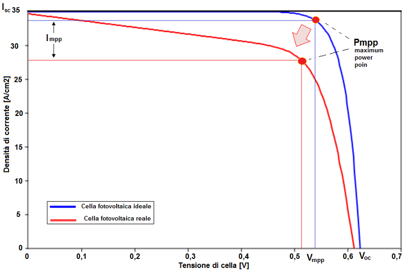
Vmpp [V]: is the voltage that is established at the ends of the photovoltaic module (set by the inverter) that allows the delivery of maximum power. On data sheets it is measured when outside there are STC conditions (1000 W / m2 of solar irradiation and 25 ° C of cell temperature)
Impp [A]: it is the current that the panel delivers when it is in the conditions of STC and has at its head the maximum power voltage
The Voc and Isc quantities are respectively the open circuit voltage and the short-circuit current of the panel already defined before.
The resistances of the electric model mean that the current voltage characteristic of the photovoltaic module is no longer "clean" as theoretically, but is deformed when these two impedances vary. The following figure presents a theoretical I-V curve compared to a real one obtained by introducing two typical values of series and parallel resistance.
ANALYSIS OF PHOTOVOLTAIC MODULES IN REAL PV PLANTS
Let's see what are the main checks to be performed on a real photovoltaic module, in operation, on a photovoltaic field. As analyzed in the previous theoretical notes, the measurement / calculation of the Fill Factor of the panel becomes fundamental, ie determining how much the I-V characteristic of the photovoltaic module deviates from that of an ideal pure cell.
The survey of the I-V characteristic curve also gives us information about the loss of performance that the panel may have suffered over time, compared to the characteristics declared by the manufacturer in the technical data sheet.
Let's see in this regard what are the main characteristic parameters of a photovoltaic module, taking into account that all the electrical characteristics of a panel are referred to the STC test conditions (Standard Test Conditions) defined by the IEC / EN 60904 standard, or 1000W solar radiation / mq, cell temperature 25 ° C, spectral distribution AM = 1.5
- Coefficient of variation of the Isc (short circuit current) indicates the variation of the intensity of the short circuit current when the working temperature of the photovoltaic cell varies. Generally expressed in %/K (percentage on degrees Kelvin) is a positive value. It allows us to calculate the Isc at the actual working temperatures of the cell.
- Voc variation coefficient (open circuit voltage) indicates the variation of the open circuit voltage value when the working temperature of the photovoltaic cell varies. Generally expressed in %/K (percentage on degrees Kelvin) is a negative value. It allows us to calculate the Voc at the actual working temperatures of the cell.
- Coefficient of variation of the Pmmp (power at the point mpp) indicates the variation of the power when the working temperature of the photovoltaic cell varies. Generally expressed in% / K (percentage on degrees Kelvin) is a negative value. It allows us to calculate the Pmmp at the actual working temperatures of the cell.
- NOCT temperature: the NOCT is defined as the operating temperature at which the cell is brought in the case of air temperature Te, NOCT = 20 °C; GNOCT irradiation = 800 W / m2; wind speed 1 m / s; module resting on a surface, therefore absence of thermal convection on the lower surface.
- Power tolerance indicates how far the maximum power of the photovoltaic module from the nominal power can deviate. The best modules have a tolerance on power only, which typically was -0 / + 3%.
On the basis of these main construction parameters of the photovoltaic modules, declared in the factory data sheet, it is possible to compare the measurements measured and the rating characteristics. So let's see how to perform this type of measures and how to determine the compliance with the factory parameters of the photovoltaic module.
![]() CONTACT US FOR TECHNICAL ANALYSIS OF YOUR PHOTOVOLTAIC PLANT
CONTACT US FOR TECHNICAL ANALYSIS OF YOUR PHOTOVOLTAIC PLANT
We are available for individuals and installers for technical inspection and expertise also for legal disputes use.
Contact us info@st-ingegneria.com

BROCHURE - REFERENCES

OUR SERVICES