PHOTOVOLTAIC CHECK-UP
![]()

PV MODULE PERFORMANCE TEST
Analysis of the modules I-V characteristic, efficiency measurement and insulation, thermographic analysis.

DC INSULATION AND CONTINUITY TEST
Analysis and checks on the DC side of a plant. Verification of Continuity and Insulation Resistance.

COMPLETE TEST OF PHOTOVOLTAIC PLANT
Testing of an entire photovoltaic system. Measurement of global losses of the photovoltaic system.
![]()
FLUORESCENCE PV MODULE TEST
Pv module Fluorescence test on site, for cracks, EVA degradation and delamination detection.

PID POTENTIAL INDUCED DEGRADATION
PID (Potential Induced Degradation). Problem description and methods for photovoltaic modules testing.

PV MODULES ELECTRO LUMINESCENCE
Outdoor Electroluminescence on site for photovoltaic modules. Case studie and methodology.

PV PLANT DRONE THERMOGRAPHY
Execution of photovoltaic modules thermography with drone. Layout of thermal defects.

SURVEY OF FTV MODULES SERIAL NUMBERS GEO-REF
Serial number survey of large photovoltaic modules. Georeferenced with AutoCAD drawings and system information.
IN FIELD ELECTROLUMINESCENCE OF MODULES AND PHOTOVOLTAIC STRINGS

We are able to offer the Electroluminescence service of high resolution photovoltaic modules and strings for an easy identification of the photovoltaic modules affected by PID (Potential Induced Degradation) effect, cell connection bus breakages, cell fractures (cracks) , damaged module bypass diodes and much more.
WHAT IS AND HOW THE ELECTROLUMINESCENCE TEST WORKS
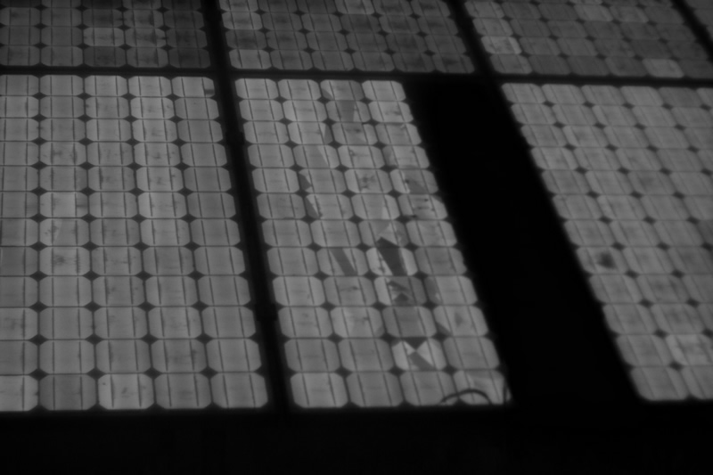
This test is based on the reverse process of photovoltaics: a voltage is applied to the modules to check the current flows, while a chamber with special sensors makes the infrared light emitted by the cells visible to the naked eye. Working cells will look bright, while damaged cells will appear dark. The test is to be considered positive only for the modules that demonstrate a uniform distribution of the current.
By sending a counter-polarization current into a photovoltaic module, a slight light emission is obtained in the infrared region of the electromagnetic spectrum. It is possible to photograph this phenomenon through a camera that has been specially modified for this use with IR mink. Since the infrared radiation emitted by the sun is much higher than that of a solar cell, this type of analysis can be performed only at night. Until recently it was possible to carry out electroluminescence tests only in the laboratory or inside the production lines of photovoltaic cells and modules, but from today it is possible to conduct these tests directly in the field.
With the electroluminescence test, the following photovoltaic module problems can be detected:
• Malfunctioning of bypass diodes (break or short circuit)
• Micro-cracks in solar cells
• PID Effect (Potential Induced Degradation)
• Ribbon contact defects (front contacts on cells)
Below is an example of the PID effect found on a real case study: 6.0 MWp PLANT (in ROME - Italy)

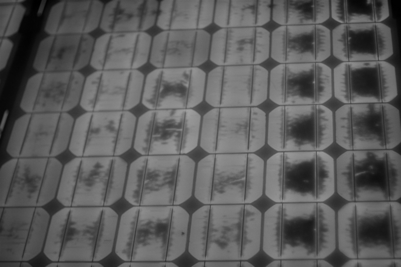
Below is an example of the CRACK CELL and BYPASS DIODE found on a real case study: 2.3 MWp PLANT (in MACERATA - Italy)
Below is an example of the DARK SPOT effect found on a real case study: 1.5 MWp PLANT (in CATANIA - Italy)
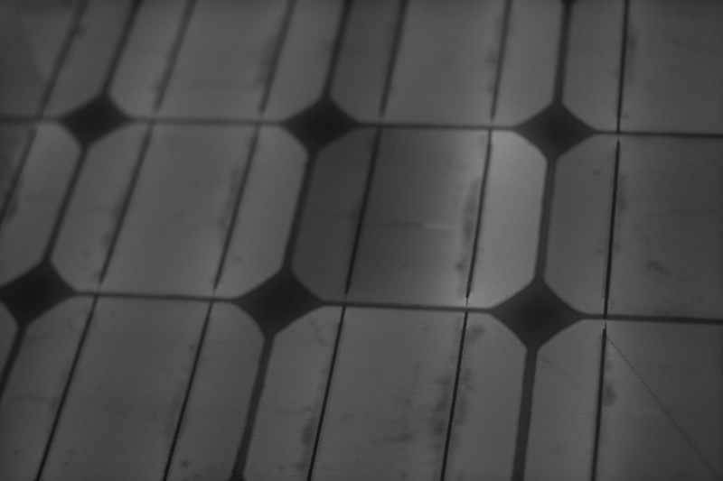
Below is an example of a DEFECTIVE RIBBON effect found on a real case study: 1.5 MWp PLANT (in CATANIA - Italy)
![]() CONTACT US FOR TECHNICAL ANALYSIS OF YOUR PHOTOVOLTAIC PLANT
CONTACT US FOR TECHNICAL ANALYSIS OF YOUR PHOTOVOLTAIC PLANT
We are available for individuals and installers for technical inspection and expertise also for legal disputes use.
Contact us info@st-ingegneria.com

BROCHURE - REFERENCES

OUR SERVICES