ELECTRICAL GRID CHECK-UP
![]()

PV MODULE PERFORMANCE TEST
Analysis of the modules I-V characteristic, efficiency measurement and insulation, thermographic analysis.

DC INSULATION AND CONTINUITY TEST
Analysis and checks on the DC side of a plant. Verification of Continuity and Insulation Resistance.

COMPLETE TEST OF PHOTOVOLTAIC PLANT
Testing of an entire photovoltaic system. Measurement of global losses of the photovoltaic system.
![]()
FLUORESCENCE PV MODULE TEST
Pv module Fluorescence test on site, for cracks, EVA degradation and delamination detection.

PID POTENTIAL INDUCED DEGRADATION
PID (Potential Induced Degradation). Problem description and methods for photovoltaic modules testing.

PV MODULES ELECTRO LUMINESCENCE
Outdoor Electroluminescence on site for photovoltaic modules. Case studie and methodology.

PV PLANT DRONE THERMOGRAPHY
Execution of photovoltaic modules thermography with drone. Layout of thermal defects.

SURVEY OF FTV MODULES SERIAL NUMBERS GEO-REF
Serial number survey of large photovoltaic modules. Georeferenced with AutoCAD drawings and system information.
ANALYSIS OF CIVIL AND INDUSTRIAL ELECTRICAL PLANT PARAMETERS WITH FV
Both in the civil and above all in the industrial sector, the quality of electricity is of fundamental importance today. Even more so with the advent of renewable energy plants which, connected to the public electricity grid, depend, in their correct functioning, on a good quality of the public network itself. We can state that in general the quality of the electricity service takes into consideration:
• continuity of power supply, understood as the absence of interruptions in the supply of electricity;
• the quality of the voltage, understood as the quality of the waveform (amplitude, frequency, variations, etc.).
There are numerous factors that affect the quality of electricity and in particular:
• employees of the Distributor (management and operation of the network, maintenance, ...);
• Customer dependent (failures at the customer's facility, disturbances issued on the network, ...);
• independent (environmental factors, atmospheric events, damage caused by third parties, ...)
So let's see quickly what may be the main disturbances that occur in an electrical supply. They are enclosed in the following image:
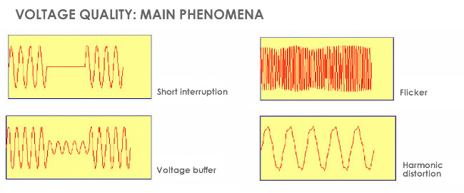
SHORT INTERRUPTIONS: Voltage interruptions are called short if less than 3 minutes, otherwise they are defined as long. Generally, 70% of short breaks last for less than 1 s. The limits imposed by the standard are generic. Long interruptions are not allowed more than 50 a year, excluding those programmed.
VOLTAGE BUFFERS: Holes are defined as the events in which the effective value of the voltage falls below 90% compared to the nominal one, for a time between 10 ms and 1 minute. The standard indicates generic limits in terms of the number of events a year, from a few tens to a thousand, depending on the type of supply. The source of voltage dips must be sought in the event of faults or of particular maneuvers or of overcurrents due to the insertion of high loads. The effects include malfunctions of electronic equipment, intervention of undervoltage relay and switch off of gas discharge lamps.
FLICKER: The flicker is a phenomenon produced by sudden and repetitive variations in tension. It is due to the frequent insertion and disconnection of the loads and manifests itself as a disturbance with a visual impression of instability on the luminance of the luminaires. The Standard requires that the long-term severity of the flicker's noise intensity, measured according to the CEI EN 60868-0 Standard (Classification CEI 110-14) is not higher than 1 for 95% of the time.
HARMONIC DISTORTION: The harmonics introduce a distortion in the original shape of the sine wave. They have a multiple frequency compared to the fundamental frequency at 50 Hz. For example, the third harmonic has a frequency of 150 Hz; that is to say three times the fundamental one. The fifth harmonic has a frequency of 250 Hz, and so on. The Standard requires that the total harmonic distortion THD (Total Harmonic Distortion) does not exceed 8%, taking into consideration up to the 40th harmonic. In addition, the effective voltage values for each harmonic must comply with the limits of the Standard for 95% of each supply week. These values are averaged over those measured within 10 minutes. The origin of the harmonics is essentially the action performed by non-linear loads, such as static converters, variable speed drives, arc welding machines, controlled diode power controls, etc. Effects attributable to harmonics In general terms, current harmonics are able to reduce the efficiency of an electrical system, damage its insulators (on lines and utilities) and create operating anomalies on different components. A particular effect, due to the presence of the third harmonic (the most important for amplitude), is that of the neutral overload.
FREQUENCY VARIATIONS: The European frequency of 50 Hz must be maintained for 95% of the supply year within a tolerance of ± 1%, while, at any time, it must not exceed an increase of 4% or a decrease of 6%. As a mean value, the Standard assumes that measured within a 10 s interval. What is at the origin of a frequency variation are the failures in the generation and transmission system, or even the sudden deactivation of large generators. The negative effects occur in terms of variation in engine speed and possible functional anomalies on electronic equipment.
UNBALANCE OF VOLTAGES: Under normal conditions, the supply voltages are symmetrical and the loads are balanced. In case of faults (breakage of the insulation) and interruptions of phases, there are disimmetries and unbalances. Moreover, with single-phase loads, the balance can only be statistical. On the basis of this, we obtain that every three-phase system, however disymmetrical and unbalanced, can be decomposed into three three-phase systems, which lead to the separate study of three single-phase circuits, corresponding respectively to the direct sequence, to the reverse sequence, to the homopolar sequence. . The EN50160 standard defines, in relation to the LV electrical systems, that "under normal operating conditions for each period of one week, 95% of the effective average values, calculated in 10 minutes, of the reverse sequence component of the supply voltage must be in the range between 0 and 2% of the direct sequence component ".
All these phenomena can affect if connected to the public electricity grid we are in the presence of a renewable energy plant like a photovoltaic system. It is therefore important to perform a thorough analysis of the electricity grid in case of problems or malfunctions of our system.
![]() CONTACT US FOR TECHNICAL ANALYSIS OF YOUR PHOTOVOLTAIC PLANT
CONTACT US FOR TECHNICAL ANALYSIS OF YOUR PHOTOVOLTAIC PLANT
We are available for individuals and installers for technical inspection and expertise also for legal disputes use.
Contact us info@st-ingegneria.com

BROCHURE - REFERENCES
OUR SERVICES